If you’ve ever spent time troubleshooting inaccurate tank level readings, you know how critical a properly mounted ultrasonic tank level sensor is to everything from chemical processing to water treatment, food and beverage storage, and even agricultural grain holding. Over the 12 years I’ve been supplying ultrasonic tank level sensors to clients across industries, I’ve seen too many projects go sideways not because the sensor itself was faulty, but because it was mounted wrong. This isn’t rocket science, but it requires attention to small, often overlooked details that make the difference between reliable 0.5% accuracy readings and data gaps that lead to costly overflows, process shutdowns, or wasted product. Today, I’m walking you through every step of mounting an ultrasonic tank level sensor, from pre-installation checks to post-calibration tips, drawing on real experiences from clients I’ve worked with and common mistakes I’ve helped fix. Ultrasonic Tank Level Sensor

First, let’s start with the basics: what an ultrasonic tank level sensor does, for context. Unlike pressure sensors that sit at the bottom of a tank and can corrode over time or get clogged by debris, ultrasonic sensors mount externally or at the top of a tank, sending high-frequency sound waves down to the surface of the liquid or solid inside. The time it takes for the wave to bounce back tells the sensor how far it is from the material surface, and subtracting that distance from the total tank height gives you the exact level. Because of this line-of-sight function, mounting is non-negotiable—block that line of sight, and your readings will be off, sometimes by multiple feet in extreme cases.
Before you even grab your drill, there are three pre-mounting checks to do that will save you hours of rework later. First, confirm your sensor’s operating range matches your tank size. I can’t tell you how many times a client has ordered a 10-meter sensor for a 5-meter tank, thinking it’s “better to have extra range,” but in reality, oversizing a sensor leads to longer signal processing times and more background noise from the tank walls. Second, check the tank’s internal structure. Does your tank have baffles, heating coils, agitators, or a metal liner? These all reflect sound waves, and if they’re in the path between the sensor and the tank bottom, they’ll cause false readings. Third, confirm the material compatibility of your sensor’s housing and transducer. For example, if you’re mounting a sensor on a tank holding harsh industrial chemicals, you’ll need a PVDF or stainless steel transducer, not a standard ABS plastic one that could degrade over time. I always send my clients a pre-installation checklist with these details before they even pick up the sensor, because skipping this step is the number one cause of returns that aren’t actually the sensor’s fault.
Once you’ve confirmed all pre-requisites are met, the next step is choosing the right mounting location. This is where I’ve seen the most mistakes over the years. The ideal spot is in the center of the tank’s top dome, 6 to 12 inches away from any internal or external walls, pipes, or fittings. Why? The center gives the most direct, unobstructed line of sight to the tank’s bottom, avoiding the edges where sound waves can bounce off tank walls and create multiple return signals. For smaller tanks (under 10,000 gallons), even a slight offset from the center can work, but for larger tanks, never mount off-center— I once worked with a municipal water treatment plant that mounted their sensor 2 feet off-center on a 50,000-gallon storage tank, and they were getting 18-inch level discrepancies for six months until we repositioned it.
If your tank has an inlet or outlet pipe at the top, never mount the sensor directly above or within 3 feet of it. When liquid pours into a tank, it creates turbulence, bubbles, and surface waves that distort ultrasonic readings. The same goes for agitation ports or pressure relief valves—any opening that disrupts the smooth surface of the material inside will cause false returns. One client in the food and beverage industry learned this the hard way: they mounted their sensor 1 foot above a wine inlet, and during harvest season, the splashing and foam from the incoming grapes made their readings bounce so much the automated filling line kept overflowing. We repositioned the sensor 5 feet away from the inlet, and that issue was resolved immediately.
Now, if you’re mounting on an external tank (no top hatch, for example, like many underground storage tanks or older industrial tanks), the rules change a bit, but line of sight still applies. Mount the sensor on the side of the tank, mid-height, 12 to 24 inches away from any welds, straps, or external pipes that could interfere with the sound wave. External mounting sensors work by passing sound through the tank wall, so you’ll need to make sure the wall is smooth, clean, and free of rust or paint that could block the signal.
Next up: choosing the right mounting hardware. This is another area where cheap shortcuts cause problems. You have two main options: a fixed mounting bracket for tanks with a top hatch, or a clamp-on mounting kit for external tanks or tanks where drilling isn’t an option. Let’s break both down. For top-mounted tanks, a heavy-duty stainless steel bracket is the best choice, because it’s corrosion-resistant and keeps the sensor steady in windy outdoor conditions (critical for tanks sitting outside in places like the Plains, where wind can cause even a slightly loose sensor to shift). Avoid plastic brackets, especially for high-temperature applications, because they can warp over time and throw the sensor’s alignment off. If you’re drilling into a tank top, make sure you use a non-conductive gasket between the mounting flange and the tank to avoid electrical interference—this is a small part that most people forget, but it prevents static or electrical noise from the sensor’s signal.
For clamp-on mounting, make sure your kit includes a rubber coupling that matches the tank wall material (steel, plastic, fiberglass) and a torque wrench to tighten the clamps to the manufacturer’s specifications. I’ve seen clients over-tighten clamp-on sensors, which can distort the tank wall and cause the sound signal to scatter, or under-tighten them, leading to movement that changes the angle of the sensor over time. Most of my clamp-on kits come with pre-marked torque settings, so all you have to do is follow them—no guesswork needed.
Wait, what about angle? Oh right, the sensor’s tilt is make-or-break. A common mistake I see is mounting the sensor dead-level with the tank top, which sounds right, but if the tank’s bottom has a slight slope (which most do), the dead-level sensor might be pointing at the center of the slope instead of the lowest point, leading to readings that are lower than actual. The correct tilt is 2 to 5 degrees off-level, pointed slightly toward the tank’s bottom slope. How do you calculate that? For a standard cone-bottom tank, measure the horizontal distance from the sensor mounting spot to the point directly above the tank’s lowest drain. The tilt angle is arctangent (slope height over horizontal distance) – in plain terms, that means if your tank’s cone drops 2 feet over a 10-foot horizontal distance, you tilt the sensor 11.3 degrees? Wait no, hold on, let me correct that for clarity: actually, for most applications, a 2-5 degree tilt is sufficient to ensure the sound wave reaches the lowest point without bouncing off the opposite wall. I like to tell clients to place a level on the sensor’s transducer housing, then tilt it just enough to align with a reference point at the bottom of the tank (we provide a simple reference card for this in every sensor box) — that avoids over-tilting, which can cause the wave to reflect off the opposite side of the tank before it reaches the bottom.
Once the sensor is mounted, it’s time to run the wiring, another step that’s often rushed and causes headaches later. Ultrasonic sensors are low-voltage, so they’re susceptible to electrical noise from power lines, pumps, or other industrial equipment. Never run the sensor’s power or signal wiring in the same conduit as high-voltage power cables—keep them at least 12 inches apart, and if you have to cross, cross at a 90-degree angle to minimize interference. Also, use shielded cable for the signal line, and ground the shield at only one end (the sensor end, not the control panel end) to avoid ground loops that create static. I always advise clients to leave extra wiring at both the sensor and the control panel, because if you ever need to reposition the sensor, or add a junction box for maintenance, having extra wire saves you from having to splice long runs later.
After wiring comes calibration, which is how you make the sensor’s readings accurate for your specific tank. Calibration is not a one-size-fits-all process, so I walk every client through it over a quick call, but here are the key steps. First, enter your tank’s full height into the sensor’s control settings—this is the distance from the sensor’s mounting reference point to the tank’s absolute bottom, not the distance to the edge of the top hatch. Second, perform an empty calibration: open the tank and confirm the material level is at zero (empty), then run the sensor’s zero calibration function. Third, perform a full calibration: fill the tank to its maximum operational level (not overfill, but the level you plan to use 95% of the time), then run the full calibration. For solids like grain or powder, you might need to adjust the gain setting, which controls how sensitive the sensor is to the return signal—powdery materials can scatter sound waves, so a slightly higher gain will help the sensor pick up the return. For liquid with foam, a lower gain is better, because foam scatters the wave and creates false returns.
Once calibration is done, run a test to make sure everything is working. I always recommend doing a manual level check with a tape measure, then comparing it to the sensor’s reading. If there’s a discrepancy, don’t panic—9 times out of 10, it’s a quick adjustment, not a faulty sensor. Common test issues include signal noise from nearby equipment, a slightly off tilt, or a calibration that was entered incorrectly. If you notice the reading fluctuating randomly, check the line of sight—something might have blown into the tank opening and is blocking the wave, or a nearby pipe is vibrating and creating false signals. If the reading is consistently off by a few inches, recheck the tilt and the calibration numbers.
Now, let’s talk about common post-installation maintenance tips to keep your sensor working long-term. Even with perfect mounting, dust, dirt, and condensation can build up on the transducer over time, blocking the sound wave. Every 3 months (or more often in dusty environments like grain silos), wipe the transducer with a soft, dry cloth—never use harsh chemicals, as they can scratch the transducer’s surface and distort the sound. For outdoor sensors, check the mounting bracket annually to make sure it’s still tight and not corroded, especially in coastal areas where salt air can cause rust. Also, if you make any changes to the tank, like adding a new baffle or a heating coil, you’ll need to recheck the line of sight and possibly re-calibrate the sensor.
Over the years, I’ve had clients come to me with sensor readings that were way off, and half the time, the fix was just re-aligning the sensor or cleaning the transducer. It’s not about having the most expensive sensor—its performance depends almost entirely on how well you mount it. I mentioned earlier that I supply ultrasonic tank level sensors, and that’s because I’ve seen the difference a well-mounted sensor makes: no overflows, no process downtime, accurate inventory tracking that saves thousands of dollars in lost product. If you’re planning a new installation or replacing an old sensor and want to make sure it’s done right, feel free to reach out to discuss your specific application, tank size, and environment—we can walk through every step together to avoid common mistakes.
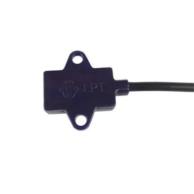
I’ve learned that the best way to build long-term relationships with clients isn’t just selling a product, it’s giving them the knowledge to make that product work for them. Mounting an ultrasonic tank level sensor doesn’t have to be complicated, but it does require taking the time to check every detail, from the mounting location to the wiring to the calibration. Skip the shortcuts, follow these steps, and you’ll have a reliable sensor that will serve you for years.
Flow Meter References
- Ultrasonic Level Measurement Fundamentals, Automation Industry Association, 2021
- Tank Level Sensor Installation Best Practices, National Association of Water Companies, 2020
- Material Compatibility Guidelines for Industrial Sensors, Sensor Technology Institute, 2022
- Calibration Procedures for Ultrasonic Tank Sensors, International Society of Automation, 2019
Shenzhen Fineherc Technology Co., Ltd.
As one of the most experienced ultrasonic tank level sensor suppliers in China, we’re featured by quality products and low price. Please feel free to buy discount ultrasonic tank level sensor made in China here from our factory. Welcome to view our website for more information.
Address: 5th Floor, Building D, No. 39, Keji East Road, Torch Development Zone, Zhongshan City,China
E-mail: fineherc@hotmail.com
WebSite: https://www.fineherc.com/
