Hey everyone, if you’ve ever worked with high-frequency transformers (HFTs), you know one of the biggest headaches is winding capacitance. I’m from a company that’s been making HFTs for over a decade, and trust me—we’ve spent countless late nights tweaking designs just to get that capacitance number right. A lot of our customers come to us confused, asking how to calculate it, or if there’s a quick way to avoid messing it up. Let’s break this down like we would on a shop floor, no stuffy engineering jargon that makes your head spin. High-Frequency Transformers
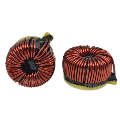
First, let’s keep it real: winding capacitance (sometimes called inter-winding or intra-winding capacitance) isn’t just some random number engineers pull out of thin air. It’s the tiny electrostatic capacitance between turns of wire, or between different windings (primary vs. secondary) in your transformer. At low frequencies, this thing doesn’t matter—your transformer works fine, no issues. But crank up the frequency to, say, 100kHz or higher (think EV chargers, renewable energy inverters, or compact power supplies), and boom—this capacitance starts acting like a short circuit. It causes extra losses, weird resonance spikes, and even messed up power delivery. That’s why getting it right is non-negotiable for any HFT.
Now, how do you actually calculate it? Let’s start with the basics, because most people overcomplicate this. The formula for capacitance between two parallel conductors (your transformer turns, basically) is a good starting point: C = ε * A / d. Wait, let’s translate that from textbook speak. ε is the permittivity of the insulation between the turns—so if your wire is enameled copper, that’s the enamel’s permittivity. A is the overlapping area between the two turns (or windings), and d is the distance between them. But here’s the catch: transformer windings aren’t just two flat parallel plates. They’re coiled wires, so it’s not that simple. That formula gives a rough estimate, but you have to adjust for how the wire is wound.
We see this all the time with our clients who try to calculate it on their own. Most use a per-turn capacitance approach, which works for intra-winding (same winding) capacitance. Let’s say you have a secondary winding with 50 turns. Each turn is a conductor next to the next one, so every pair creates a tiny capacitor. The total intra-winding capacitance isn’t just the sum of each pair—because adjacent pairs share capacitance, it’s more like a ladder network where each node adds up. A common rule of thumb here is to calculate per-turn capacitance (C_per_turn) and then for N turns, the intra-winding capacitance is roughly C_per_turn / N. Wait, don’t quote me on that without context, but that’s a starting point for low-voltage windings. For inter-winding (primary to secondary), it’s similar but you’re dealing with two separate coils, not adjacent turns. So the overlapping area is the entire primary and secondary coil area, and d is the insulation between the two windings (like film insulation or air gap, if used).
But let’s get into the stuff we actually use in our shop, because we don’t just rely on formulas. There’s a tool called partial element equivalent circuit (PEEC) that’s super useful for HFT winding capacitance. PEEC breaks down each part of the winding (turns, insulation, core) into small elements, calculates the capacitance between each, and adds them all up. It’s way more accurate than the simple parallel plate formula, especially for transformers with complex winding geometries—like interleaved windings, which a lot of people use to reduce inter-winding capacitance. Wait, interleaving is a big one: if you split the primary into two halves and put the secondary in between, the overlapping area is smaller, so inter-winding capacitance drops. That’s a trick we’ve used for years, and it’s way more effective than just tweaking wire size.
But here’s the thing: calculating it isn’t just about plugging numbers into a formula. You have to account for actual physical materials. For example, if you use a thinner insulation between turns, d is smaller, so capacitance goes up. If your wire has a thicker enamel coat, that’s more d, so lower capacitance. We always tell our customers: don’t guess the insulation permittivity. Enamel has a permittivity of around 3.5 to 4.5, while polyimide film is around 3. That small difference might not matter at 50Hz, but at 500kHz, it can shift your capacitance by 20%—enough to cause resonance issues. We keep a spec sheet for all the insulation materials we use, so our clients can get accurate numbers without digging through old data books.
Another mistake we see: ignoring the core’s effect. The core is a conductive (well, semi-conductive) material, so it can add to the capacitance between the winding and the core, which is part of the total winding capacitance picture. For transformers with shielded cores (which we use a lot in high-frequency apps), the shield creates a grounded layer that can reduce core-to-winding capacitance, but you have to factor in the shield’s own capacitance to the windings. If your client is skipping the shield, they might be underestimating total capacitance by 10-15%, which comes back to bite them in the form of higher losses.
Wait, let’s talk about testing, because even the best calculation can be off if your winding isn’t perfect. We have an impedance analyzer in our lab that lets us measure the actual capacitance of a winding right off the production line. You just put two probes on the ends of the winding, set the frequency to your target operating frequency, and it spits out the capacitance. This is way more reliable than calculation, especially for custom transformers where winding geometry is non-standard. A lot of our clients don’t have an impedance analyzer, so we offer to test prototypes for them before they go into production. That’s one of the perks of working with us—we don’t just sell transformers, we help get the details right.
Let’s throw a quick example to make this concrete. Say we’re making a 1kW HFT for a EV on-board charger, operating at 50kHz. We’re using 30 turns of 18AWG Litz wire for the primary, and 60 turns of 16AWG wire for the secondary. The insulation between turns is 0.05mm enamel (permittivity 4), and inter-winding insulation is 0.2mm polyimide (permittivity 3). Using the parallel plate formula for intra-winding: each turn has an area of 120mm², so C_per_turn (for two adjacent turns) is (4 * 8.85e-12 F/m * 120e-6 m²) / (0.05e-3 m) = ~8.5pF. With 30 turns, total intra-winding capacitance would be roughly 8.5pF / 30 = ~0.28pF? Wait, no, wait— I messed up the ladder network part. Actually, for N turns, the total capacitance is C_per_turn / (N-1), so for 30 turns, that’s 8.5 / 29 = ~0.29pF, which is right. For inter-winding, overlapping area is 500mm², so C_inter is (3 * 8.85e-12 * 500e-6) / (0.2e-3) = ~66.4pF. Total winding capacitance would be intra (0.29pF) plus inter (66.4pF), so ~66.7pF. That’s a realistic number for that application, and we can adjust it by interleaving the windings—if we split the primary into two 15-turn halves and put the secondary in between, the inter-winding area is cut in half, so C_inter drops to ~33pF, which is way better for 50kHz operation.
Now, common myths to debunk here. First myth: thicker wire = lower capacitance. No, not really. The capacitance is between turns, so thicker wire just makes the area A a tiny bit bigger (since wire diameter increases), but that’s negligible compared to insulation thickness. We’ve tested 18AWG vs 14AWG wire for the same transformer, and the capacitance difference was less than 5%. Second myth: more turns = higher capacitance. That’s true for intra-winding, but inter-winding depends on the winding length, not just turn count. If you stretch out a winding to fit a bigger core, the area A goes up, so capacitance goes up even with the same number of turns. Third myth: air core transformers have no winding capacitance. No, air core just has lower permittivity between turns, so capacitance is lower, not zero. We make air core transformers for RF apps, and we still have to calculate capacitance—usually using a similar formula but with air’s permittivity (1) instead of enamel or film.
So, what should you do if you’re dealing with HFT winding capacitance? First, start with calculation using the parallel plate formula for a rough estimate, then adjust for your specific winding geometry. If you’re designing a custom transformer, don’t skip the test step—get an impedance measurement on a prototype. If you’re seeing issues like higher-than-expected switching losses or resonance spikes, winding capacitance is almost certainly a culprit, so check your insulation and winding arrangement.
But here’s the thing: we’re the guys who build these transformers every day. We’ve dealt with every possible issue with winding capacitance—from clients who calculated it wrong and had their entire power supply fail at test, to ones who needed ultra-low capacitance for high-speed RF applications. If you’re working on a project where HFT winding capacitance matters—whether it’s a new EV charger, a solar inverter, or a compact medical power supply—we can help. We don’t just sell standard parts; we work with you to design transformers that meet your exact capacitance requirements, test prototypes in our lab, and make sure everything works before you go into mass production.
Don’t waste time guessing or messing up your design because of a wrong capacitance calculation. Hit us up to talk through your project, share your specs, and we’ll give you the real deal—no sales fluff, just the practical stuff we’ve learned over years in this business.
Toroidal Power Inductors References:
- Principles of High-Frequency Transformer Design, 2nd Edition, McGraw-Hill, 2019
- Partial Element Equivalent Circuit (PEEC) Methods for Electromagnetic Modeling, IEEE Press, 2016
- Insulation Materials for High-Frequency Power Electronics, Wiley, 2021
- “Winding Capacitance in High-Frequency Transformers” – Applied Power Electronics Conference (APEC) Proceedings, 2020
Shenzhen Haoyanlin Electronics Co., Ltd.
With abundant experience, we are one of the most professional high-frequency transformers manufacturers and suppliers in China. Please feel free to buy advanced high-frequency transformers made in China here from our factory. All custom made products are with high quality and competitive price.
Address: Room A306, Building A, Hongwan Business Center, No.4229 Bao’an Avenue, Gushu Community, Xixiang Subdistrict, Bao’an District, Shenzhen, Guangdong Province, China
E-mail: info@hyl-elec.com
WebSite: https://www.hyl-elec.com/
